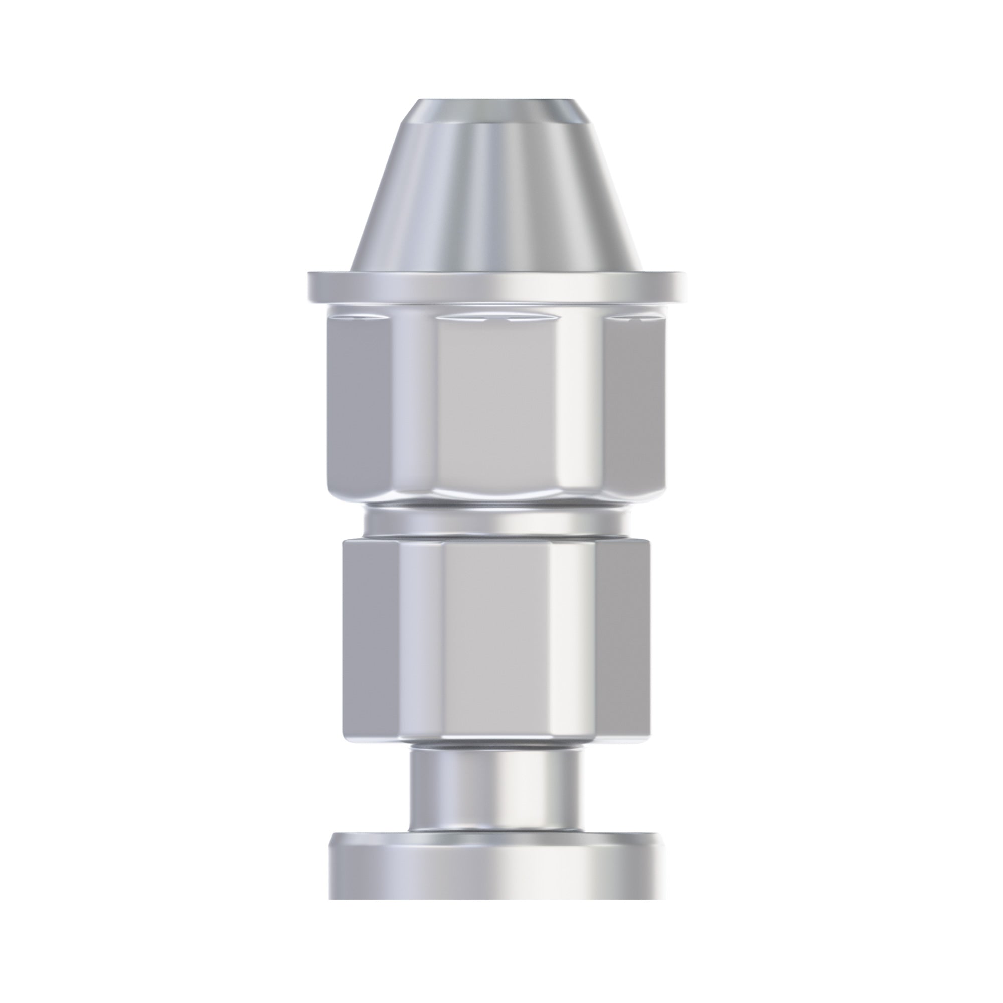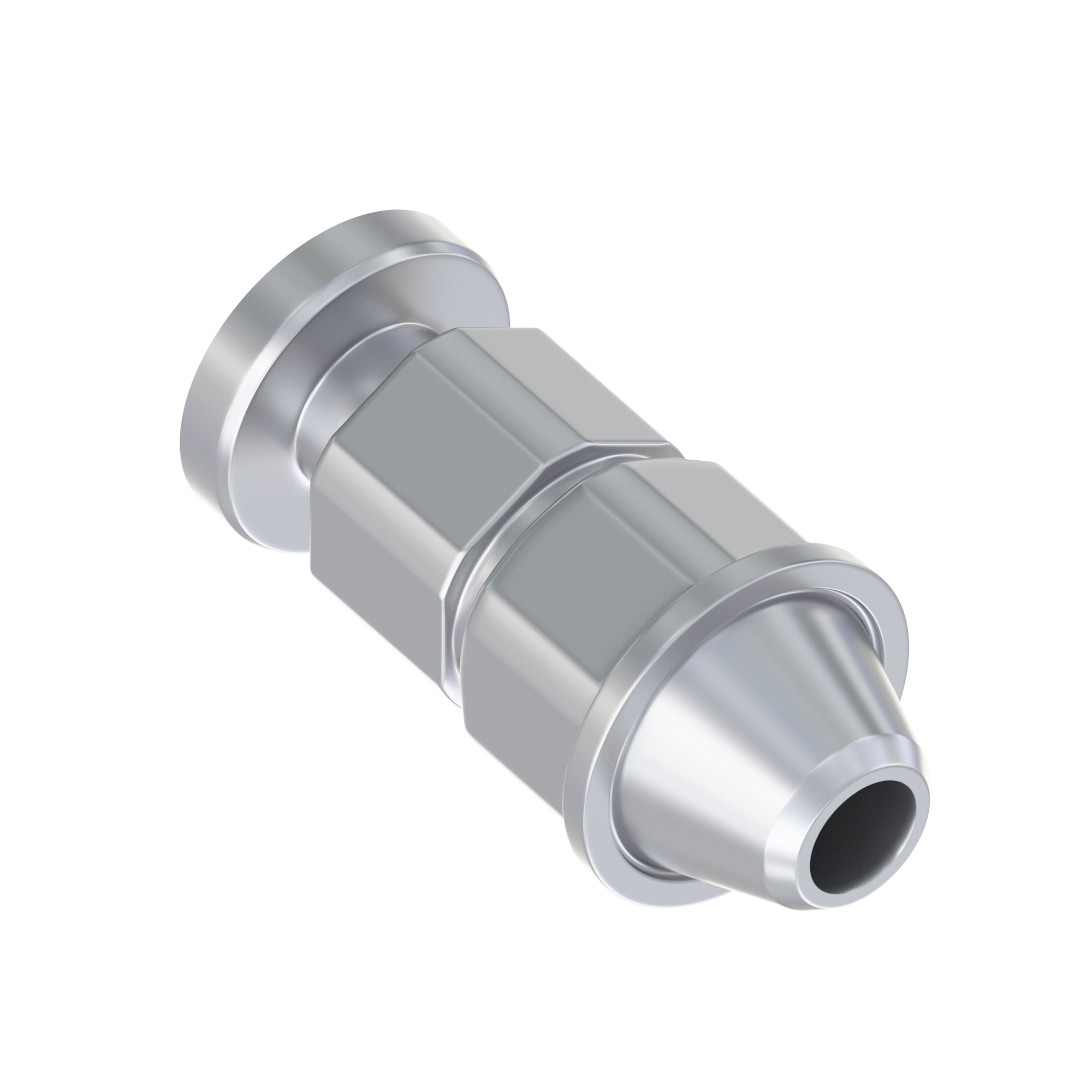

Whenever an implant case is worked on a physical model, one small component stands in for the implant: the lab analog. It reproduces the connection geometry from the mouth in the working model, and every abutment, coping, and screw that follows is seated against it.
When an analog is ordered for the wrong interface, the error is not always obvious on arrival. It shows up later, at try-in, when a restoration fabricated on the model does not seat the same way in the mouth. This guide covers how laboratories and restorative clinicians identify the correct analog before the order is placed.
What the analog has to reproduce
A lab analog replicates the coronal portion of the implant or the abutment: the connection geometry, the platform diameter, and the internal thread. It does not replicate the implant body, the thread design, or the surface treatment, because none of those affect the restorative interface.
The analog is selected by the interface, not by the brand name
A frequent ordering error is treating the manufacturer's name as sufficient information. A single manufacturer typically produces several connection families and several platform diameters across its range, and an analog matched to one is not interchangeable with another.
The identifiers that matter are the exact implant system, the connection geometry, the platform, and, for multi-unit cases, the abutment interface rather than the implant interface. A nominal diameter on its own is not enough, because systems sharing a connection name can still differ in indexing, taper, and thread. This is the same selection logic that governs abutment choice, covered in more detail in our guide to conical connection versus internal hex implants at the prosthetic stage.
Where a mismatch becomes visible
A mismatched analog can sometimes still accept a screw and still hold an abutment on the model, which is how the problem passes a quick inspection. Rotational indexing, seating depth, and emergence position are the properties that diverge.
All three can be checked on the model itself, and they should be, because a discrepancy found on the cast costs a component while the same discrepancy found at try-in costs the restoration.
Verifying the platform against the surgical record before ordering is faster than remaking a restoration. Where the implant identification is uncertain, it should be confirmed before any laboratory component is ordered.
Reading the connection before ordering
Three interface groups cover a large share of restorative work, and other implant systems use further geometries such as external hex, tri-lobe, and tri-channel. Identifying which group applies narrows the selection to a small number of parts.
Internal hex: narrow 2.00 mm and standard 2.42 mm
Internal hex connections are widely used across implant systems, and within the compatible families covered here the practical distinction for the laboratory is the hex width: a Ø2.00 mm hex on the narrow connection and a Ø2.42 mm hex on the standard connection. These figures describe these families rather than defining narrow and standard universally, so the implant system itself should still be confirmed.
For cases confirmed as standard platform 2.42 mm internal hex, the DIP Standard Platform Analog Wide Body, Internal Hex Ø2.42 mm is the matching part. For confirmed narrow platform cases, the DIP Narrow Platform Analog, Internal Hex Ø2.00 mm is the corresponding part.

Conical connection: NP and RP
Conical connections seat on a system-specific tapered interface rather than a flat platform, and many of them combine the cone with indexing or shoulder features that all have to be fully seated. NP and RP are restorative platform designations rather than measurements, and the implant diameters they serve differ by system: in the compatible family carried here, NP covers Ø3.5 mm implants while Ø4.3 mm and Ø5.0 mm implants share the RP connection.
The DIP Standard Analog for Conical Connection RP Ø4.3 to 5.0 mm is the RP option, with an NP equivalent for narrow platform cases.
Multi-unit analogs: M1.4, M1.6 and M1.7
Full-arch and angulated cases change the question. When a multi-unit abutment is already in place, the laboratory is reproducing the abutment interface, not the implant connection, so the analog is selected against that abutment system.
M1.4, M1.6 and M1.7 are the thread designations used to group these multi-unit components, and they are not interchangeable. The designation identifies the thread rather than the whole interface, so the abutment family and its mating geometry should be confirmed alongside it. The DIP Standard Analog for Multi-Unit M1.7 is one of the three, alongside M1.4 and M1.6 versions. The selection logic behind these interfaces is set out in our article on M1.4 multi-unit abutments for angulated and digital restorations.

Standard analogs and 3D digital analogs
The second decision is the model workflow. A standard analog is set into stone or plaster; a digital analog is designed to be inserted into a printed model, with a retention geometry that locks into the printed socket.
| Property | Standard analog | 3D digital analog |
|---|---|---|
| Model type | Stone or plaster poured from a physical impression | Printed model generated from a scan file |
| Retention | Retained by the poured material around the body | Mechanical retention into the printed socket |
| Workflow entry point | Conventional impression with a transfer | Intraoral or model scan with a scan body |
| Library requirement | None | Matching CAD library for the socket geometry |
| Typical use | Conventional workflows built on poured models | Digital workflows built on printed models |
Choosing between the two
The workflow determines the analog, not the other way around. A laboratory pouring a conventional impression typically uses a standard analog, and a printed model that takes an inserted analog calls for a digital analog whose geometry matches the library used at the design stage.
Where a printed model is planned, the library compatibility should be confirmed before ordering, because the socket geometry in the printed model has to correspond to the analog being seated into it.

Body shape: short body and wide body
Beyond the connection, analogs vary in body form. A wide body gives more retention in the model material and resists rotation in the stone. A short body is used where model height is limited, most often in sectioned or removable die work.
Both forms carry the same connection geometry, so the choice is driven by the model rather than by the restoration.
Analogs for components already in the case
Some cases do not call for an implant-level analog at all. When the restoration is built on an attachment or an abutment that stays in the mouth, the analog has to reproduce that component instead.
Overdenture attachment analogs
Overdenture work is the clearest example. A ball attachment, a Loc-in attachment, and a low-profile hybrid attachment each present a different geometry to the denture, and each has its own analog for the working model. Selecting the analog by the attachment already placed, rather than by the implant beneath it, is the correct approach.
Compatible components and analog selection
Where a case is restored with compatible components, the analog is chosen against the platform those components seat on. dip dental™ supplies analogs compatible with the major implant systems, including Neodent GM® Grand Morse, MegaGen AnyRidge®, NobelActive®, Zimmer®, Astra Tech® EV, and Biomet 3i Certain®, at a significantly more competitive price than the original manufacturers' components.
dip dental™ is not affiliated with, endorsed by, or a distributor for any of these companies. Why the platform match matters more than the label on the box is covered in the real reason brand compatibility matters when ordering implant parts.
Ordering checklist for the laboratory
Before an analog order is placed, confirm the following:
- Connection type: internal hex, conical connection, tri-lobe, or a multi-unit interface.
- Implant system and platform: the exact system and platform, not the manufacturer's name alone.
- Restorative level: implant level or abutment level.
- Multi-unit interface: the abutment family and its thread designation, M1.4, M1.6 or M1.7, where a multi-unit abutment is in place.
- Model workflow: poured stone model or printed model.
- Library compatibility: confirmed for any digital analog.
- Body form: standard, wide body, or short body, according to model height.
Working through the list takes a minute and removes a frequent cause of a remake. Related component selection is covered in our guide to dental abutments for dental professionals.
Frequently Asked Questions
What is the difference between a lab analog and a digital analog?
A lab analog is set into a poured stone or plaster model, while a digital analog is inserted into a printed model and held by mechanical retention in the printed socket. Both reproduce the same connection geometry; the difference is how the model is produced and how the analog is retained in it.
How do I know which analog matches my implant platform?
Use the surgical record to confirm the exact implant system, its connection geometry, and its platform, rather than the manufacturer's name alone. A single manufacturer usually offers several connection families and several platform diameters, and an analog for one will not correctly reproduce another.
Do multi-unit restorations need a different analog?
Yes. When a multi-unit abutment is in place, the analog reproduces the abutment interface rather than the implant connection, so it is selected against that abutment family and its thread designation, M1.4, M1.6 or M1.7. The designations are not interchangeable.
Can one analog be used across several implant brands?
Only where those systems genuinely share the same connection geometry and platform diameter. Some platforms are dimensionally common across manufacturers, but this should be verified for the specific systems in the case rather than assumed from the connection name.
What is the difference between a short body and a wide body analog?
Both carry identical connection geometry, and the difference is the analog body below it. A wide body gives greater retention and rotational stability in the model material; a short body is used where model height is restricted, such as sectioned or removable die work.
Browse the full Lab Analogs collection for analogs across internal hex, conical connection, multi-unit and digital workflows.