A full-arch screw-retained restoration concentrates the occlusal load of an entire arch onto four to six fixtures and the dental implant parts that connect them. How that load is distributed is decided less by the implants themselves than by implant angulation, the multi-unit abutment interface, and the accuracy with which the framework seats.
This article looks at stress distribution in All-on-4® and All-on-X restorations from the restorative side: what the component choices actually control, which specifications have to be verified before ordering compatible implant parts, and where these cases fail mechanically.
Where the Load Goes in a Full-Arch Screw-Retained Bridge
A full-arch prosthesis behaves as a beam supported at discrete points. Load applied between supports is shared between them. Load applied distal to the last support acts on a cantilever and returns to the terminal implant as a magnified force.
Three geometric variables govern that transfer:
- Anterior-posterior (A-P) spread: the distance between the center of the most anterior implant and a line joining the distal implants.
- Cantilever length: how far the prosthesis extends distal to the terminal implant.
- Terminal implant angulation: the axis along which the distal implant receives that load.
The relationship between cantilever length and A-P spread is the reason distal implants are tilted at all. Moving the terminal emergence posteriorly increases A-P spread and shortens the cantilever needed to reach the first molar position.
Acceptable cantilever limits vary by protocol, arch, opposing dentition and framework material. Take them from the restorative plan for the case rather than from a general rule.
What Distal Angulation Does, and What It Does Not Do
Tilting the distal implants is a surgical decision that solves an anatomical problem. It allows a longer fixture to be engaged anterior to the mental foramen or the maxillary sinus without grafting, while moving the prosthetic emergence distally.
What it does not do is remove off-axis loading. A tilted fixture receives force at an angle to its long axis, and the resulting bending moment has to be managed at the prosthetic connection rather than eliminated. That is the job of the multi-unit abutment.
Two consequences follow for the restorative team:
- The screw-access channel of a tilted implant exits through the buccal or facial surface unless it is redirected at abutment level.
- Divergence between fixtures has to be corrected before the impression or intraoral scan, not compensated for later in the framework.
The Multi-Unit Abutment Is the Load-Transfer Interface
A multi-unit abutment (MUA) converts several individual implant connections into a single prosthetic platform, parallel across the arch and at a controlled height. Everything above it, meaning the framework, the prosthetic screws and the ceramics, engages that platform rather than the implant connection.
M1.4, M1.6 and M1.7: the screw thread on top of the abutment
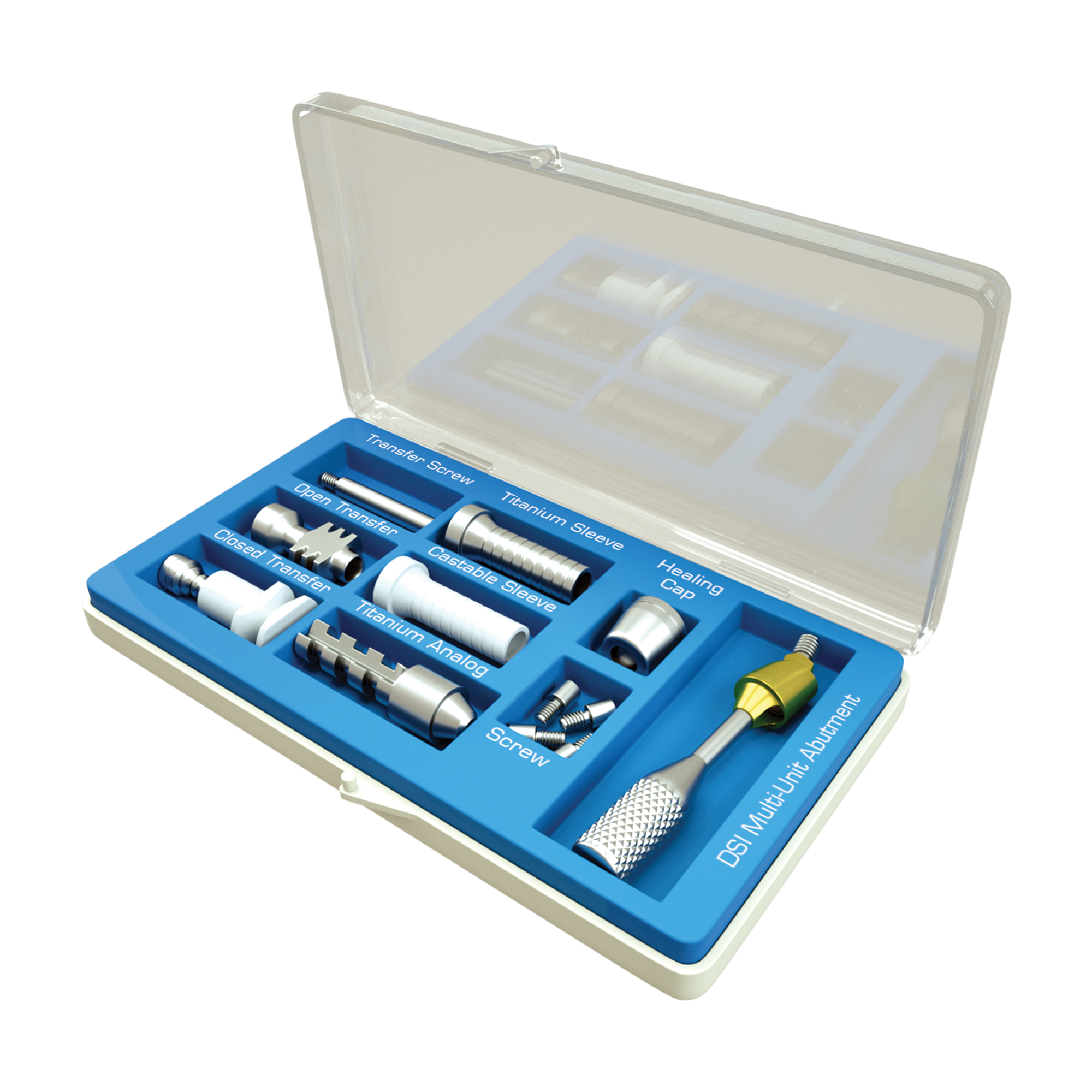
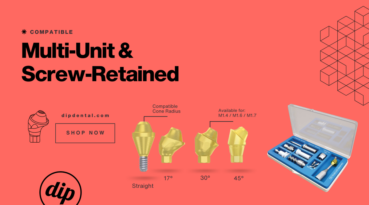
Multi-unit abutments are supplied with different screw threads on top of the abutment, designated M1.4, M1.6 and M1.7. That designation, not the implant brand, is what every prosthetic screw, transfer, analog, scan body, titanium base and CAD/CAM library above the abutment has to match.
dip dental™ carries compatible implant components for all three thread systems: Multi-Unit Abutment M1.4, Multi-Unit Abutment M1.6 and Multi-Unit Abutment M1.7, each with its matching transfers and lab analogs. Mixing a screw or a transfer from one thread system into another is one of the more common ordering errors on full-arch cases, and it is caught only at the try-in.
Correcting divergence at the abutment, not in the framework
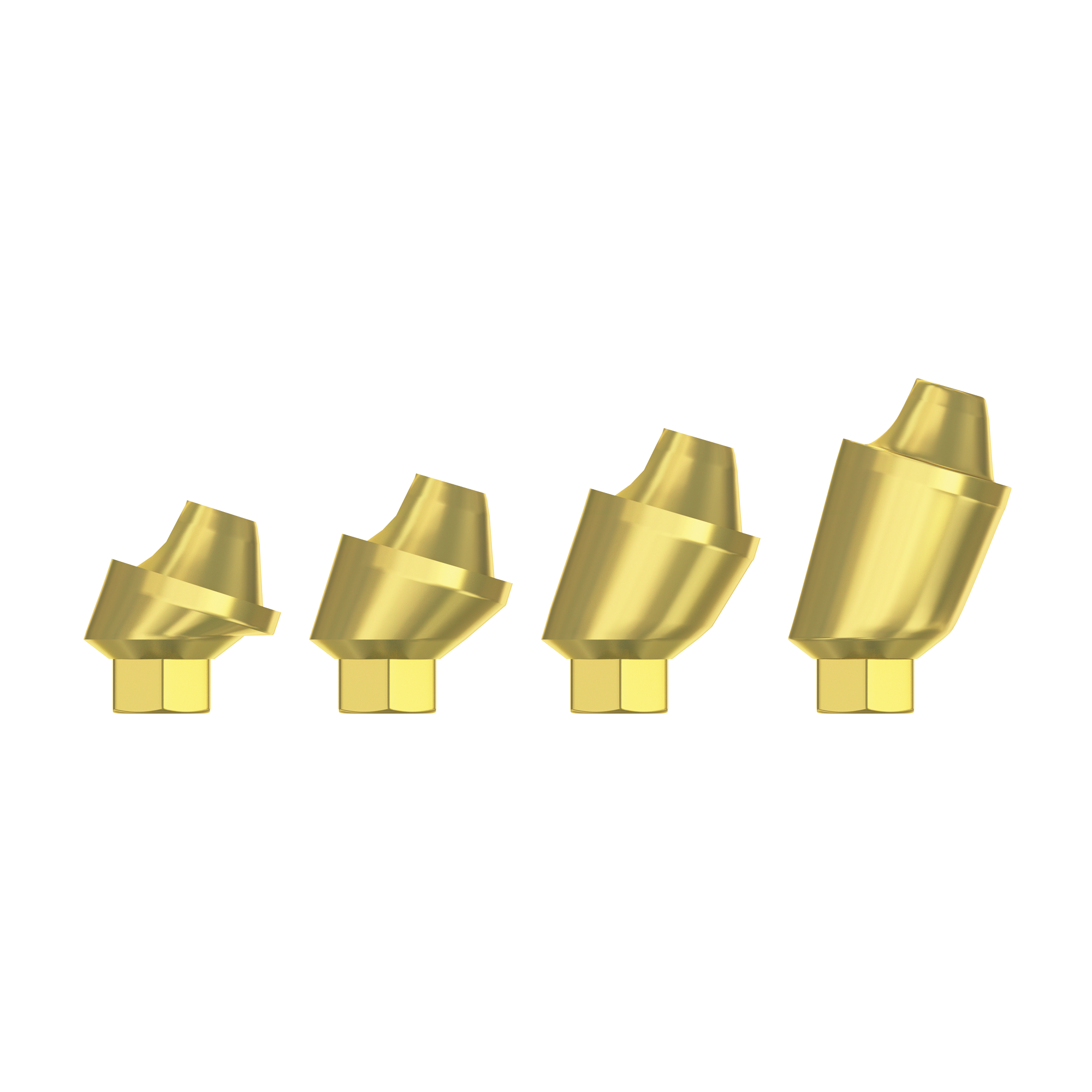
Angulated MUAs are supplied in fixed correction angles, most commonly 17°, 30° and 45°. Selecting the correction that brings every platform parallel is what allows one framework to seat without being forced into place.
A framework that is flexed to seat stores that strain permanently. It is released into the prosthetic screws, the abutment screws and the implant-bone interface under function, and it is present whether or not the patient is chewing.
dip dental™ supplies straight and angulated multi-unit abutments across internal hex and conical platforms, at a significantly more competitive price than the equivalent parts from the original manufacturers. The Multi-Unit & Screw-Retained collection holds the range; the DIP Angulated Multi-Unit Abutment (M1.7) full set is supplied in 17°, 30° and 45° corrections for internal hex RP platforms.

Angulated multi-unit abutments by platform
The correction angle is selected per implant, and the abutment itself has to match the fixture that is actually in the mouth. These are the same 17° and 30° corrections supplied as compatible implant parts for three of the platforms most often used in full-arch cases.


Gingival height and the screw-access channel
Gingival height sets where the abutment-prosthesis junction sits relative to the soft tissue. Too low and the junction is submerged, which complicates seating verification and hygiene access. Too high and vertical restorative space for the framework is lost.
Correction angle and gingival height are selected together, site by site, from the actual surgical position. Neither can be changed afterwards without removing and replacing the abutment.
Connection geometry is not interchangeable
Internal hex platforms and conical platforms differ in geometry and in platform diameter, so the abutment has to be matched to the fixture that is actually in the mouth. Compatibility here is not limited to one connection family.
dip dental™ supplies compatible implant components for many of the most widely used implant systems, including Neodent GM® Grand Morse, Straumann®, MegaGen AnyRidge®, MegaGen AnyOne®, MegaGen Blue Diamond®, Nobel Active®, Osstem® TS, Hiossen® ET, MIS® and Dentium®. For conical cases, the Conical Multi-Unit System collection and the Premium Angulated Multi-Unit Abutment (M1.6) for conical connection NP Ø3.5 mm are the relevant starting points.
dip dental™ also carries compatible implant parts for the Zimmer® internal hex platform: lab analogs for Zimmer internal hex 3.5 (SP) and Zimmer internal hex 5.7 (WP), and a pre-milled titanium abutment blank for the Zimmer 3.5 compatible RP platform, for custom CAD/CAM abutments.
Attachment-retained overdentures run on a separate component family
Where the plan is an attachment-retained removable overdenture rather than a fixed screw-retained bridge, load reaches the implant through an attachment rather than through a multi-unit platform, and every prosthetic part above it matches the attachment system instead of an MUA thread designation.
dip dental™ supplies components compatible with Zest Locator®, an attachment system used for implant-supported overdentures. The Zest Locator® compatible range holds lab abutment analogs, impression copings, metal housings and silicone retention inserts, together with straight overdenture attachment sets for the Zimmer® RP 3.5, MegaGen Mini NP, MegaGen AnyRidge® and Neodent GM® platforms.
The Fully Digital Full-Arch Workflow
A full-arch case can be taken from intraoral scan to milled or printed framework without a physical impression, provided every step in the chain refers to the same multi-unit platform definition. The digital route does not change the mechanics described above. It changes where the error creeps in, from impression distortion and model expansion to library mismatch and scan-body play.
Four matched parts carry that workflow at multi-unit level, and all four are keyed to the MUA screw thread designation, meaning M1.4, M1.6 or M1.7:
- Scan bodies, also referred to as scan posts or scan flags, screwed directly onto the multi-unit abutment. Their geometry is what the design software recognises in the scan file, so the platform position, height and rotation in the design come from the scan body rather than from the operator.
- The CAD/CAM library supplied for that scan body and that titanium base. A library from a different system with a nominally similar diameter will place the platform at the wrong height or the wrong rotational index, and the framework is designed around that error before anything is milled.
- Titanium bases and titanium sleeves, which the milled or printed superstructure is bonded to, or which are incorporated directly into a screw-retained bar.
- Digital analogs for 3D printed models, so that the printed model carries a real metal platform for seating verification rather than a printed replica of one.
dip dental™ supplies all four as compatible implant parts, in each of the three thread systems: Digital Parts for Multi-Unit holds the scan post bodies, titanium bases and 3D printing analogs for M1.4, M1.6 and M1.7, and the wider CAD/CAM & Digital collection covers implant-level scan posts and titanium bases for internal hex and conical platforms.


Where the workflow runs at implant level rather than multi-unit level, the same logic applies one platform lower: the Multi-Unit CAD/CAM Scan Body compatible with Neodent® GM, Osstem® TS and MegaGen® and the Multi-Unit Ti-Base for the Geo CAD/CAM library are matched to each other and to the library they are designed for.
Two points are worth keeping in front of the technician on every digital full-arch case. First, scanning multiple multi-unit platforms across a full arch accumulates error along the arch, so a verification step, whether a photogrammetry capture, a printed verification jig or a splinted physical index, is still worth building into the protocol. Second, passive fit is verified on the physical framework and not in the design software, which is why the digital analog in the printed model has to be a real analog.
What to Confirm Before Ordering
| Variable | What it controls | Verify against |
|---|---|---|
| Implant connection type and platform diameter | Whether the abutment seats at all | The surgical record or implant reference, not appearance on a radiograph |
| MUA correction angle (0°, 17°, 30°, 45°) | Screw-access direction and platform parallelism | Divergence measured per implant on the model or CBCT |
| Gingival height | Junction position and vertical restorative space | Soft tissue depth at each individual site |
| Abutment fixation screw and driver | Whether the abutment can be torqued to its own protocol | The MUA system specification |
| MUA screw thread designation (M1.4 / M1.6 / M1.7) | Prosthetic screws, transfers, analogs, scan bodies, titanium bases | The abutment in use, not the implant brand |
| CAD/CAM library version | Platform height and rotational index in the designed framework | The library supplied for that scan body and titanium base |
| Digital analog for the printed model | Whether passive fit can be verified on a physical model | The same MUA thread system as the scan body |
Passive Fit Overrides the Other Variables
Angulation and A-P spread distribute load in the ideal case. Framework misfit redistributes it in every case, and it does so continuously.
A framework that does not seat passively preloads the system before any occlusal force is applied. Because that preload is static rather than cyclical, it is never relieved between loading episodes.
Checks worth building into the try-in:
- Single-screw test at each terminal abutment, watching for lift-off at the opposite end of the arch.
- Radiographic confirmation of complete seating at every abutment, not only the terminal ones.
- A verification jig, or splinted open-tray transfers taken with the components in the Multi-Unit Transfers collection, for the master impression.
- On a digital case, a verification capture independent of the intraoral scan before the framework is milled.
Where fit remains doubtful, sectioning and luting the framework is a more predictable route than torquing it into position.
Where Full-Arch Cases Fail Mechanically
- Prosthetic screw loosening. Usually the first signal, and the cheapest one to read correctly.
- Prosthetic screw fracture. The system giving way at its intended weakest point. Retrieval is possible; the approach is covered in the guide to removing a broken implant screw or fractured fixture.
- Abutment screw loosening. Less frequent, harder to access, and a reason to re-examine framework seating.
- Framework or veneer fracture. Associated with cantilever length, material thickness and parafunction.
- Marginal bone loss at a terminal implant. Multifactorial, and worth reviewing alongside load distribution and the occlusal scheme rather than in isolation.
Repeated loosening at the same site is reporting something about the fit or the occlusion. Replacing the screw without changing either resets the clock rather than solving the problem.
A Verification Sequence Before You Order
- Identify the implant system, connection type and platform diameter for every fixture from the surgical record.
- Measure divergence between fixtures and select a correction angle per implant.
- Measure soft tissue depth at each site and select a gingival height per implant.
- Confirm the MUA screw thread designation, M1.4, M1.6 or M1.7, that the prosthetic screws, transfers, analogs, scan bodies, titanium bases and CAD/CAM library must all match.
- On a digital case, confirm that the library in the design software is the one supplied for the scan body and titanium base being used.
- Order fixation screws, position holders, transfers and digital parts together with the abutments, not after the try-in.
dip dental™ supplies the dental implant parts in that sequence as compatible implant components, covering both the conventional and the fully digital route, at a price that is highly competitive against the original manufacturers' equivalents.
Where the connection type itself is still open, the prosthetic differences between conical and internal hex connections are worth settling first. For M1.4 cases, the M1.4 multi-unit abutment guide covers the matching component range, and whether a titanium base is needed at all for a screw-retained connection is discussed in direct connection screws for MUA restorations.
Frequently Asked Questions
Does tilting the distal implants increase the stress on them?
Tilting changes the direction of loading rather than simply increasing it, and the angulated multi-unit abutment exists to redirect that off-axis component at the prosthetic platform. The trade-off is between the off-axis force on the fixture and the shorter cantilever that the increased A-P spread allows, and it is decided per case rather than as a rule.
Can a multi-unit abutment compensate for implants that are too divergent?
An angulated multi-unit abutment corrects divergence only up to its fixed correction angle, commonly 17°, 30° or 45°, and nothing beyond it. It does not change A-P spread, cantilever length or inter-implant distance, all of which are fixed at surgery.
What is the difference between M1.4, M1.6 and M1.7 multi-unit abutments?
The designation refers to the screw thread on top of the abutment, which determines which prosthetic screws, transfers, analogs, scan bodies, titanium bases and CAD/CAM libraries will fit above it. All three are separate, non-interchangeable systems, and dip dental™ supplies compatible implant parts for each of them.
Do the prosthetic parts match the implant platform or the abutment platform?
Above the multi-unit abutment, every part matches the MUA screw thread designation, meaning M1.4, M1.6 or M1.7, and not the implant brand. Only the abutment itself and its fixation screw have to match the implant connection type and platform diameter.
What is needed to run a full-arch case as a fully digital workflow?
A scan body for each multi-unit abutment, the CAD/CAM library supplied for that scan body, a titanium base or titanium sleeve for the superstructure, and a digital analog for the 3D printed model. All four have to belong to the same MUA thread system, M1.4, M1.6 or M1.7, and dip dental™ supplies the full set for each of the three.
Is repeated prosthetic screw loosening a torque problem?
Repeated loosening at the same site is more often a fit or occlusion problem than a torque problem. Re-torquing to the manufacturer's protocol without addressing framework seating or the occlusal scheme tends to reproduce the same failure at the same site.
What has to be verified before ordering multi-unit components for a full-arch case?
Implant connection type and platform diameter, correction angle per implant, gingival height per implant, the MUA screw thread designation for all prosthetic parts, and the CAD/CAM library version. Correction angle and gingival height cannot be changed after the abutment is torqued, so both are worth confirming twice.
dip dental™ supplies compatible implant parts to dental clinics and laboratories. All trademarks named here are the property of their respective owners and are used to describe compatibility only. This article is for educational purposes and does not replace product instructions for use, manufacturer torque protocols, or case-specific clinical judgment.